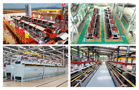
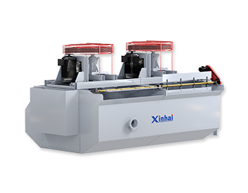
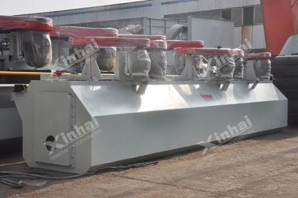
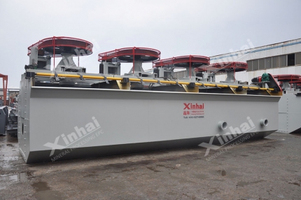
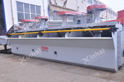
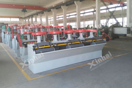
A flotation cell, also called a flotation machine or flotation tank, is the process vessel where pulp and air are mixed, valuable mineral particles attach to bubbles, and mineralised froth is separated from the tailings. In a flotation circuit, the cell is more than a passive vessel: its aeration method, agitation intensity and slurry circulation pattern affect bubble dispersion, particle suspension, flotation kinetics and reagent consumption. They also determine how the circuit is laid out on site.
Xinhai Mining supplies a complete range of flotation cells: SF, JJF, BF, XCF, KYF, XJB and CLF. This guide compares the four types most often considered side by side when selecting a flotation machine: SF, JJF, XCF, and KYF.
Use the table of contents below to navigate through the guide:
01How flotation cells are classified
Flotation cells are classified by how they aerate and agitate the pulp. Three categories cover nearly all flotation applications:
Category | How the pulp is aerated | Typical models | Advantages | Limitations |
Mechanical agitation (self-aspirated) | The impeller and stator draw air from the atmosphere; air enters near the agitation zone. | SF, JJF, BF | Self-suction of air and slurry (SF / BF); middlings can return by gravity; few auxiliary devices; compact equipment layout; simple operation and maintenance. | Low aeration volume; higher power consumption; greater wear. |
Air-inflation agitation (external blower) | A blower forces air through the hollow shaft into the impeller chamber; the agitator disperses the air. | XCF, KYF, CLF | Air volume is adjustable and remains constant, supporting capacity and metallurgical indexes. Because the impeller does not draw in air, it runs at low speed with low power and less wear; brittle minerals are less likely to be slimed. Low power consumption per tonne. | Requires a separate compressed-air system. |
Air-inflation (no agitator) | Blower only; no mechanical agitation. | Flotation column | Simple structure and easy to manufacture. | Without an agitator, flotation performance is affected. The aerator is prone to scaling, which impairs air dispersion. |
If your project also needs to determine how many flotation stages the circuit requires, and the order in which valuable minerals should be floated, see the companion guide /newo/how-to-choose-principle-process-of-flotation-process.html.
02How SF flotation cell works
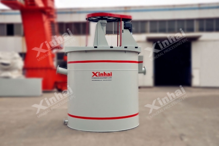
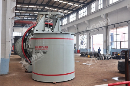
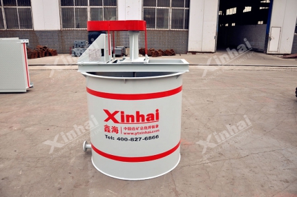
In the SF flotation cell, a motor drives the main shaft through a V-belt, rotating an impeller fitted with backward-inclined, double-sided blades. The resulting negative pressure in the upper and lower impeller chambers draws air through the suction pipe and slurry from the tank. The two phases mix between the blades to form fine mineralised bubbles, which a cover plate stabilises and disperses before they rise into the froth layer for collection by scraping.
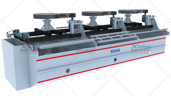
Self-suction of both air and slurry. No froth pump is needed, and middlings return by gravity.
Low impeller peripheral speed helps extend the service life of wear parts.
Large air intake at low energy consumption. The generous impeller-to-cover gap means wear has little effect on air intake.
Backward-inclined, double-sided blades create fixed upper and lower circulation loops, helping keep coarse particles in suspension.
The forward-inclined tank has small dead zones and allows froth to move quickly.
03How does a JJF flotation cell work?
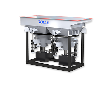
The JJF flotation cell, designed with reference to the WEMCO cell, uses vortices in the vertical and draft tubes to create negative pressure and draw in air. Air and pulp mix around the impeller and stator. The stator converts the impeller’s tangential flow to radial flow and distributes it through the cell, where mineralised bubbles rise into the froth layer.
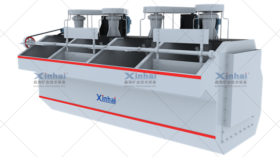
Shallow trough with a small, slow-running impeller and low power consumption.
The large impeller-to-stator gap and cylindrical stator with oval openings help air and pulp mix and disperse.
The stator sits below the impeller, creating a large circulating volume of up to 2.5 times.
An umbrella-shaped perforated dispersion cover shields the froth layer from the impeller vortex and keeps the pulp surface stable.
Mechanical agitation with self-aspiration of air but no self-priming of pulp. A ladder layout between operations is therefore essential, with a fall of 300-400 mm.
The JJF can be combined with an SF flotation cell in one unit: SF acts as the slurry suction cell and JJF as the direct-flow cell.
04How does an XCF flotation cell work?
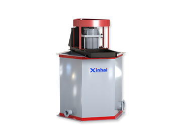
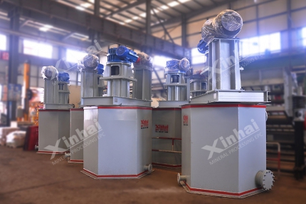
The XCF flotation cell is an air-inflation cell designed to serve as the suction cell in a KYF circuit. Its structure and performance are similar to KYF, but a stator mounted above the impeller creates a negative-pressure zone that enables slurry suction at slightly higher energy consumption. An external blower supplies air through the hollow shaft and impeller-chamber air distributor. The pulp-air mixture moves upward and outward around the upper half of the impeller, where the stator stabilises and directs the flow.
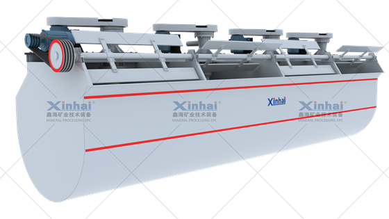
Simple structure and strong stirring capacity; air is dispersed evenly and mixes well with the slurry.
Less tailings deposition, low peripheral speed and low energy consumption.
Serves as the slurry suction cell in an XCF + KYF combined unit.
The deep tank is available in open and closed designs; the bearing body is available in seated and hanging types.
Used for roughing and scavenging in medium and large concentrators processing non-ferrous metals, ferrous metals and non-metallic minerals.
05How does a KYF flotation cell work?
In the KYF flotation cell, the impeller draws slurry from near the tank bottom while a blower supplies low-pressure air through the hollow shaft and impeller-chamber air distributor. Unlike a self-suction cell, KYF relies on an external air supply and does not draw slurry. The pulp-air mixture moves obliquely upward from the upper half of the impeller, and the stator directs it into the tank. Some slurry returns to the lower impeller zone for further agitation; the remainder passes to the next cell and eventually becomes tailings.
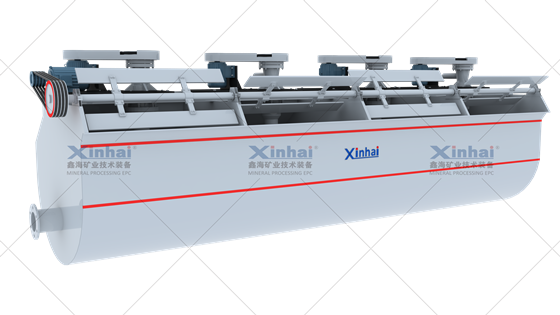
A conical impeller with backward-inclined blades provides a simple structure and strong stirring ability.
A multi-hole cylindrical air distributor in the impeller chamber disperses air evenly and promotes good mixing with the slurry.
The small impeller diameter and low peripheral speed reduce energy consumption by 30-50%.
Good ore suspension and high flotation indexes.
The U-shaped tank reduces tailings deposition and extends the service life of wear parts.
The cell does not self-aspirate air or prime slurry, so a stepped layout is required between operations. In an XCF + KYF combined unit, KYF serves as the direct-flow cell.
06How to select a flotation cell for your project
Flotation machine selection is a sizing and configuration exercise. Before choosing a model, work through the inputs below. Omitting any one of them can cause a cell to underperform after start-up.
Selection input | What it determines |
Ore type and mineralogy, supported by testwork | Whether the ore suits self-aspirated or air-inflation cells, the reagent scheme and flotation-stage arrangement. |
Target throughput (t/d or t/h) and design margin | Required cell volume and number of cells. |
Feed particle size and liberation size | Agitation intensity and air volume, and whether a coarse-particle cell such as CLF is needed for the coarse fraction. |
Pulp density, pH, temperature and reagent scheme | Circulation performance, reagent consumption and construction material. |
Product targets - concentrate grade and recovery | Number of cleaning stages and the required degree of process control. |
Circuit design: stages, flotation time, rougher/cleaner/scavenger split | Number of cells per bank and how the banks are connected. |
Plant layout, headroom and footprint | Whether a level configuration (SF or XCF + KYF) or ladder configuration (JJF or KYF used alone) is feasible. |
Power supply (voltage and frequency) and automation level | Drive option, instrumentation and control scope. |
Supply boundary, spares and wear-part policy | Scope of supply and long-term operating cost. |
Metallurgical testwork is the most valuable step. Two ores with similar head grades can behave very differently in flotation. A locked-cycle test that reproduces the intended circuit turns a capacity figure into a defensible cell selection.
07Flotation cell selection support from Xinhai Mining
Xinhai Mining Group designs flotation circuits and manufactures the cells used in them, so the same team handles both selection and engineering.
Whether you are selecting cells for a new concentrator or debottlenecking an existing flotation circuit, our engineers can compare the options against your ore and plant layout.
Talk to a flotation engineer. Send us your ore type, target throughput, feed size and product requirements. We will recommend a cell selection and circuit configuration.
08Flotation cell selection FAQs
What is the difference between an XCF and a KYF flotation cell?
Both require an external blower. XCF’s stator above the impeller creates a negative-pressure zone that primes slurry at slightly higher energy consumption; KYF cannot prime slurry. They are commonly combined, with XCF as the suction cell and KYF as the direct-flow cell.
Can SF and JJF flotation cells be used together?
Yes. SF provides slurry suction, while JJF serves as the direct-flow cell, adding its shallow trough and large circulating volume.
Which flotation cell is best for coarse particles?
A full-range air-inflation cell designed for coarse particles, such as the CLF coarse-particle flotation cell, is generally used for coarser, denser and higher-density pulp. Among the standard types, SF’s fixed dual circulation helps keep coarse minerals suspended. XCF and KYF have their own circulation patterns, which should be assessed against the actual size distribution.
Do I need a froth pump with these cells?
SF self-primes and needs no froth pump. JJF or KYF used alone requires a ladder or stepped layout; an XCF + KYF unit can run on one level without a froth pump.
 marketing@xinhaimining.com
  0086 13810327080




 CHAT
CHAT MESSAGE